 |
TRANSPOWER EQUIPMENT |

|
TRANSPOWER EQUIPMENT |
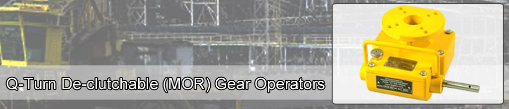
The TRANSPOWER make gear units are Q-Turn De-clutchable (MOR) Gear Operators, specially developed to operate 90° movement valves along with pneumatic actuators. Precisely machined from the tested, quality raw materials, the operators are weatherproof. The alloy steel worm engages /disengages with the worm wheel depending upon the selector level position. Whenever there is service line (Electric or pneumatic) failure, the operator is put on the "Engaged" (or "ON") mode and the valve is operated via gear operator. Generally the gear operator is put on "OFF"mode.
For manual operation of pneumatically operated quarter turn valves
in the event of service line failures.
Torque range from 60 NM to 35000 NM.
12 models available to cover the above torque range.
Shaft acceptance from 25 to 90 mm.
Valve & actuator end F10 To F30.
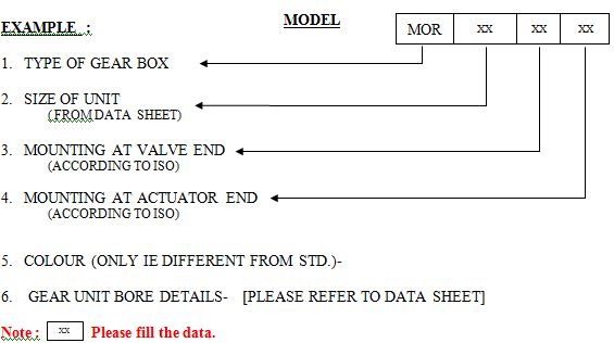
ORDERING SPECIFICATIONS FOR MANUAL OVERIDE [MOR] GEAR UNITS. -
To have definite specifications of the required Manual overide Units, we request following data while placing your order :
 |
| Download the form from the PDF file, fill it and send it to us. |  |
The Gear Units are generally manufactured & supplied as per GAD/ customer- specifications outlined in Order Acceptance [O/A]
INSTRUCTIONS FOR INSTALLATION "TRANSPOWER" Q-TURN De-CLUTCHABLE (MOR) GEAR OPERATORS
(a) Check the coupling pin dimensions and ensure they match with the gear unit being installed in the system.Address :
Transpower Equipment
Plot number 62 & 63, Swami Vivekanand Co. Op. Industrial Estate,
Handewadi Road, Satavnagar,
Hadapsar, Pune 411 028
Maharashtra. INDIA
Designed by Websenz Technologies